¶ EGBOUNDARY Command
The EGBOUNDARY command is the core command of EGBoundary used for generating intelligent boundaries from selected geometry inside supported CAD applications.
¶ Supported CAD Platforms
| CAD Software | Supported Versions |
|---|---|
| BricsCAD | V22 – V26 |
| AutoCAD | V20 – V26 |
| ZWCAD | V24 – V26 |
| GStarCAD | V24 – V26 |
¶ Command Syntax
EGBOUNDARY
Shortcut Alias:
EBDR
The command is case-insensitive.
¶ How To Use
¶ Step 1 — Open Drawing
Open the drawing in which you want to create boundaries.
¶ Step 2 — Start Command
Enter the following command in the CAD command line:
EGBOUNDARY
Press Enter.
¶ Step 3 — Select Objects or Area
Select:
- Desired geometry
OR - Entire drawing region
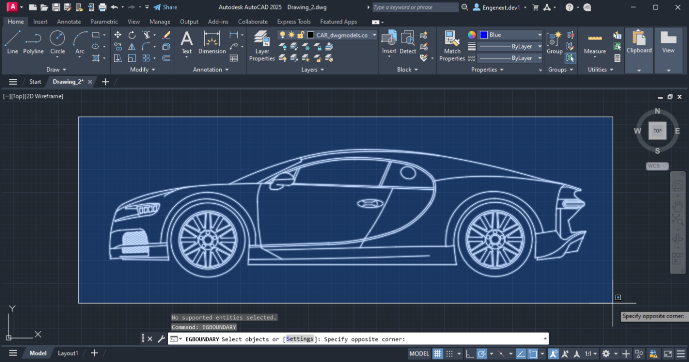
depending on workflow requirements.
¶ Step 4 — Generate Boundary
Press Enter after selection.
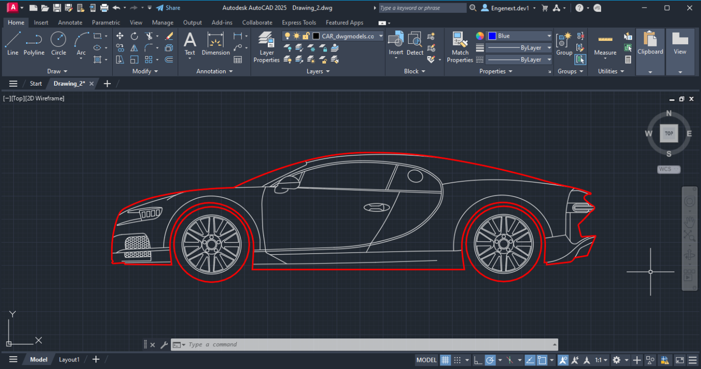
EGBoundary automatically calculates and generates the required boundaries.
¶ Key Features
¶ Multiple Island Detection
EGBoundary supports intelligent island detection.
Example:
- Outer body boundary
- Internal holes
- Multiple disconnected regions
can all be processed simultaneously.
¶ Automatic Tolerance Calculation
The software automatically calculates optimal gap tolerance values for:
- Better accuracy
- Faster processing
- Improved boundary detection
This behavior is enabled by default.
¶ Layer Control
Users can:
- Create boundaries on custom layers
- Use current active layer
- Assign layer-specific workflows
¶ Color and Linetype Support
Boundary output supports:
- BYLAYER color
- Custom colors
- Continuous linetype
- Dotted linetype
- Custom line styles
¶ Wipeout Generation
EGBoundary supports automatic wipeout creation during boundary generation workflows.
¶ Settings Command Integration
While running EGBOUNDARY, users can access advanced settings.
During object selection:
Enter:
S
to open the Settings dialog.
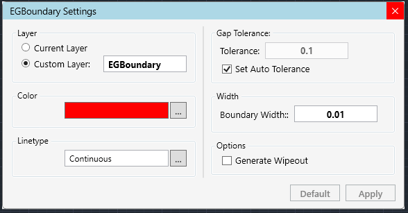
This allows customization of:
- Colors
- Linetypes
- Boundary width
- Layer name
- Manual tolerance
- Wipeout options
¶ Best Practices
For optimal results:
- Use clean geometry
- Minimize open gaps
- Use automatic tolerance whenever possible
- Avoid extremely fragmented entities
¶ Common Issues
¶ Boundary Not Generated
Possible reasons:
- Open geometry
- Invalid selection
- Unsupported entities
¶ Recommended Solution
- Increase tolerance
- Clean drawing geometry
- Retry selection
¶ Slow Processing
Large drawings with excessive entities may increase processing time.
¶ Recommended Solution
- Process smaller regions
- Simplify geometry
- Close unnecessary applications
¶ Example Workflow
- Open CAD drawing
- Run:
EGBOUNDARY
- Select desired entities
- Press Enter
- Generated boundaries appear automatically
¶ Related Commands
| Command | Description |
|---|---|
EGBOUNDARY |
Generate intelligent boundaries |
EBDR |
Shortcut alias for EGBOUNDARY |
EGABOUT |
Product and license information |
EGLOGIN |
Open license login dialog |
¶ Notes
- Command is case-insensitive
- Supports multiple CAD platforms
- Works in both trial and licensed modes
¶ Support
For technical support or assistance: