¶ Settings Command
The Settings functionality in EGBoundary allows users to customize boundary generation behavior according to drawing and workflow requirements.
Settings can be accessed directly while running the EGBOUNDARY command.
¶ Purpose of Settings
The Settings dialog provides control over:
- Boundary appearance
- Layer configuration
- Linetype selection
- Boundary width
- Tolerance behavior
- Wipeout generation
This helps users generate boundaries that match project standards and CAD workflows.
¶ How To Open Settings
¶ Step 1 — Start EGBOUNDARY
Enter the following command in the CAD command line:
EGBOUNDARY
Press Enter.
¶ Step 2 — Start Selection
The command will prompt for object selection.
At this stage:
- Before selecting objects
OR - After selecting objects
enter:
S
Press Enter.
¶ Step 3 — Settings Dialog Opens
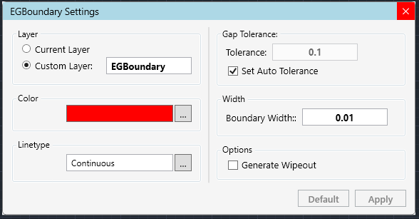
The EGBoundary Settings dialog will appear with multiple customization options.
¶ Available Settings
¶ Boundary Color
Users can select:
- BYLAYER color
- Custom colors
This controls the final generated boundary color.
¶ Boundary Width
Boundary line width can be customized according to drafting requirements.
Useful for:
- Visibility improvements
- Plotting standards
- Layer-based drafting workflows
¶ Custom Layer Name
Users can:
- Create boundaries on existing layers
- Assign custom layer names
- Use current active layer
This helps maintain organized CAD drawings.
¶ Linetype Selection
Supported linetypes include:
- Continuous
- Dotted
- Dashed
- Custom loaded linetypes
¶ Wipeout Generation
EGBoundary supports automatic wipeout creation during boundary generation.
Useful for:
- Masking geometry
- Presentation drawings
- Annotation clarity
¶ Tolerance Settings
¶ Automatic Tolerance (Recommended)
By default:
Automatic Tolerance
is enabled.
EGBoundary automatically calculates optimal gap tolerance values for better performance and accuracy.
¶ Manual Tolerance
Users may disable automatic mode and manually define gap tolerance values.
Recommended only for:
- Complex drawings
- Extremely small gaps
- Special drafting workflows
¶ Applying Settings
After adjusting settings:
- Click:
Apply
- The dialog closes
- Continue selecting entities
- Press Enter to generate boundary using selected settings
¶ Recommended Workflow
- Start:
EGBOUNDARY
- Open Settings using:
S
-
Configure:
- Layer
- Color
- Tolerance
- Linetype
-
Apply settings
-
Select geometry
-
Generate boundary
¶ Best Practices
For optimal results:
- Use Automatic Tolerance whenever possible
- Keep layer naming consistent
- Use BYLAYER properties for standard drafting workflows
- Avoid excessive manual tolerance values
¶ Common Issues
¶ Boundary Not Accurate
¶ Solution
- Enable Automatic Tolerance
OR - Increase manual tolerance slightly
¶ Linetype Not Visible
¶ Solution
- Verify linetype is loaded in CAD
- Regenerate drawing
- Adjust linetype scale
¶ Wipeout Not Displayed
¶ Solution
- Use REGEN command
- Verify wipeout display settings in CAD
¶ Related Commands
| Command | Description |
|---|---|
EGBOUNDARY |
Generate intelligent boundaries |
S |
Open settings during EGBOUNDARY |
EGABOUT |
Product and license information |
EGLOGIN |
License login dialog |
¶ Supported CAD Platforms
| CAD Software | Supported Versions |
|---|---|
| BricsCAD | V20 – V26 |
| AutoCAD | V24 – V26 |
| ZWCAD | V24 – V26 |
| GStarCAD | V24 – V26 |
¶ Support
For technical assistance: